The Process Simulator tool is designed to understand the basics of model estimation, model analysis, controller design, tuning techniques and process simulation. The state of the art simulator can be used to understand the features and effect of PID parameters. This tool helps in two major areas like, to understand the process behaviour and to visualize the impact of controller design. The following process behaviour and controller design can be studied:
| Processes | Control Algorithms |
|
|
|
|
|
|
|
|
|
|
|
|
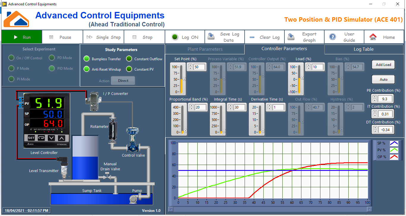
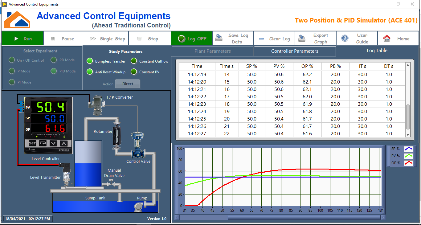
Two Position & PID Simulator
This state of the art tool utilizes the mathematical model of a level tank and simulates closed loop level control. It eliminates the need of a hardware system and mimics the working of a real level control plant. First principle model is used and user can modify the process parameters as per their requirements. This tool aids in understanding level control with PID and On/Off controller. The software simulator will be used to understand servo and regulatory responses of the level plant.
List of Experiments
|
|
|
|
|
|
|
|
|
|
|
|
Screenshots
|
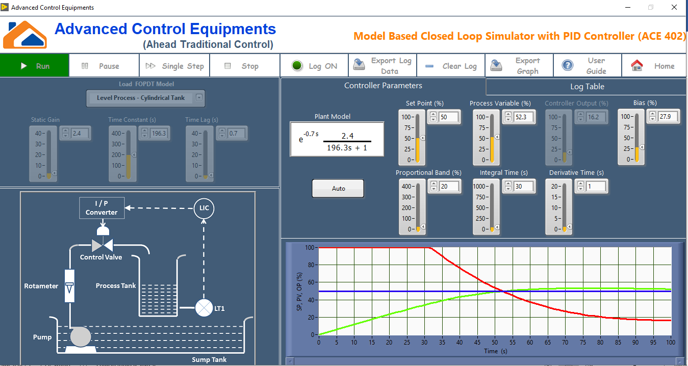
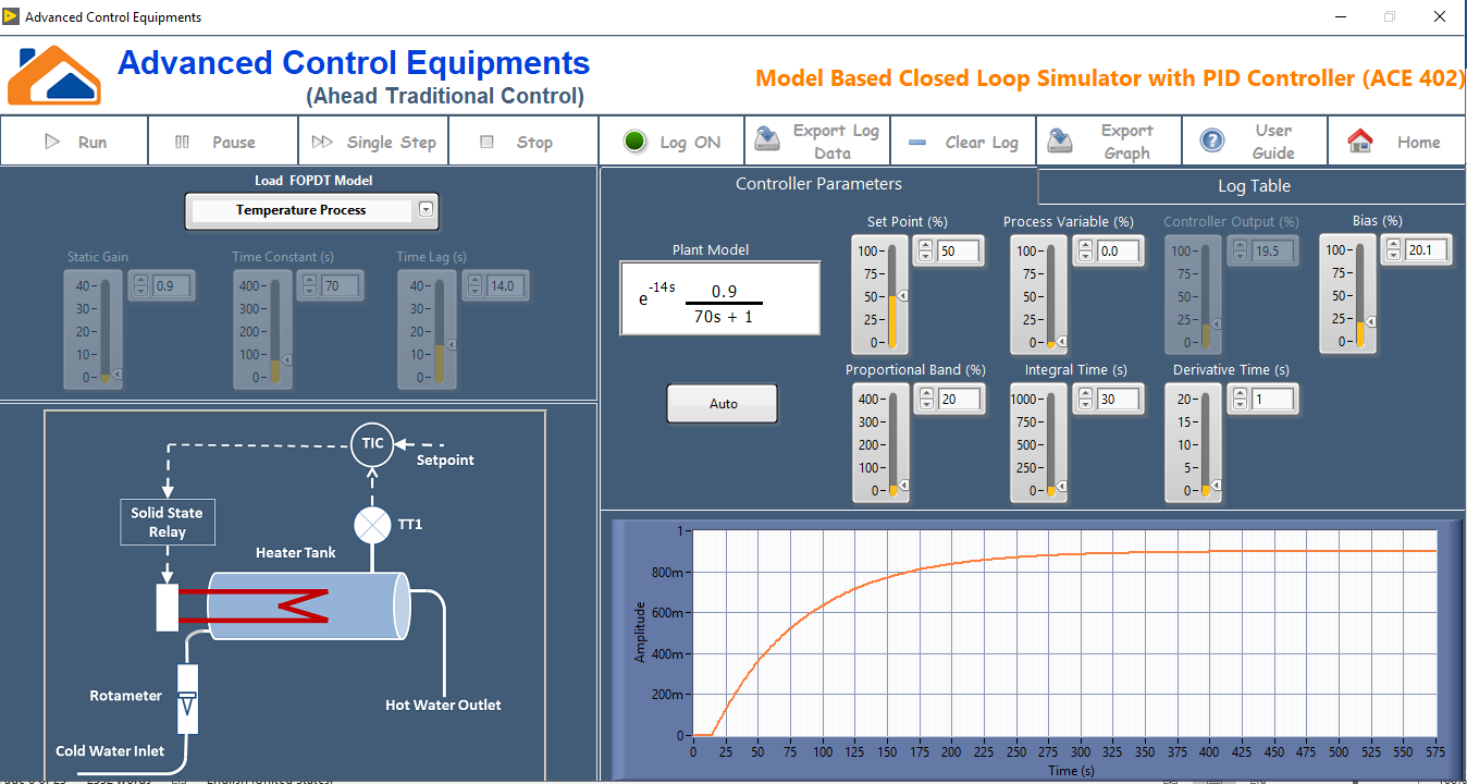
Model based Closed loop simulator with PID controller
This tool simulates the mathematical model and implement closed loop control with PID controller. It is aimed to demonstrate different process plants and its behavior. A set of models are pre-loaded and can be selected to perform the experiment. The inbuilt models are extracted from empirical model identification of a typical laboratory setup. Along with the pre-build models, user can experiment with custom models and observe the response with PID controller. The pre-build model includes,
|
|
|
|
|
|
|
|
List of Experiments
|
|
|
|
|
|
Screenshots
|
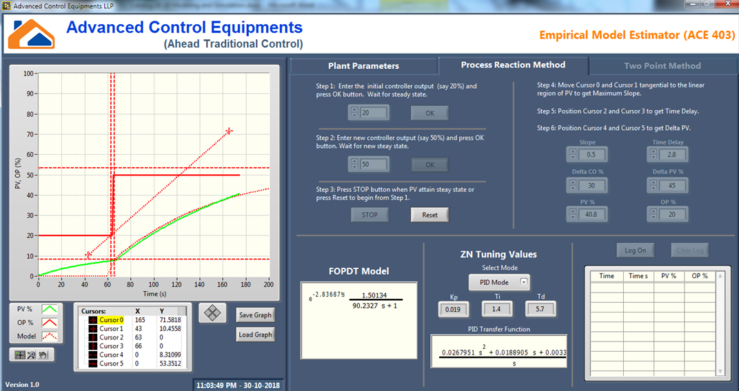
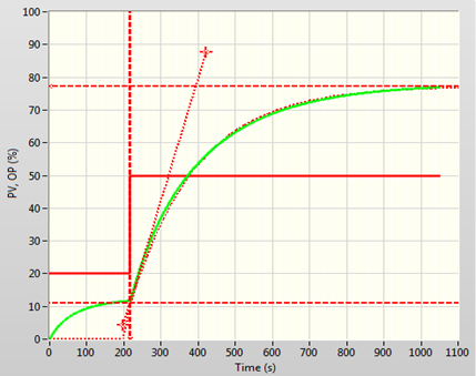
Empirical Model Estimator
This tool explains the procedure of empirical (data driven) model estimation of a level plant. A typical level plant used in Two Position & PID simulator (ACE 401) package is used in this tool. Three methods namely Process Reaction method, Classical method and Two position method can be used in this tool to estimate the model. A step input is applied to the open loop system and the response is observed. With the aid of graph cursors, the slope, delay and gain will automatically be calculated and the transfer function will be estimated. The transfer function model response will also be plotted on the graph to validate the model. The slope and amplitude values can be adjusted to obtain a good fit between plant response and the transfer function model response.
Features
|
|
|
|
|
|
|
|
Screenshots
|
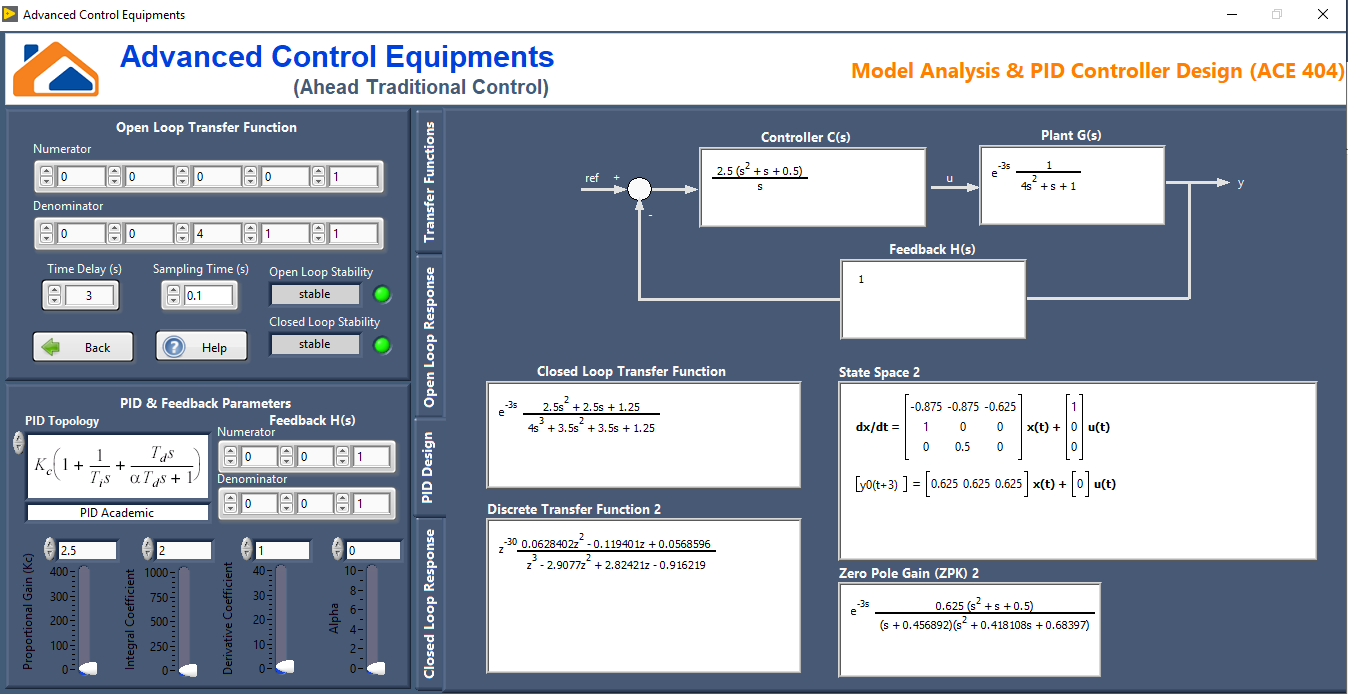
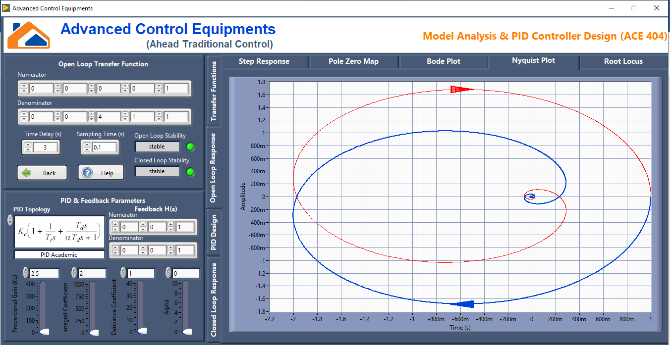
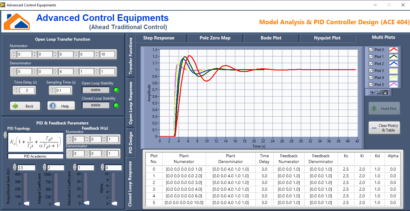
Model Analysis & PID Controller Design
This tool is designed to understand the PID controller response for a plant transfer function. User can understand the importance of a feedback system with PID control for a stable, unstable and marginally stable system. It can also be used to understand an unstable open loop system can be made stable using proper PID design and a stable open loop system can be made unstable by improper PID design. This tool also display the various forms of transfer function representation such as pole zero form, discrete form and state space forms of open loop and closed loop systems. It also displays the response of open and closed loop system in the form of step response, bode plot, Nyquist plot and pole zero map. A user interactive root locus design can also be performed. This tool also comes out with a state of the art multi plot option to hold the graph for different transfer function and different set of PID values. User can understand the impact of each of the PID parameter variation by observing the response plot.
Features
|
|
|
|
|
|
|
|
Screenshot
|
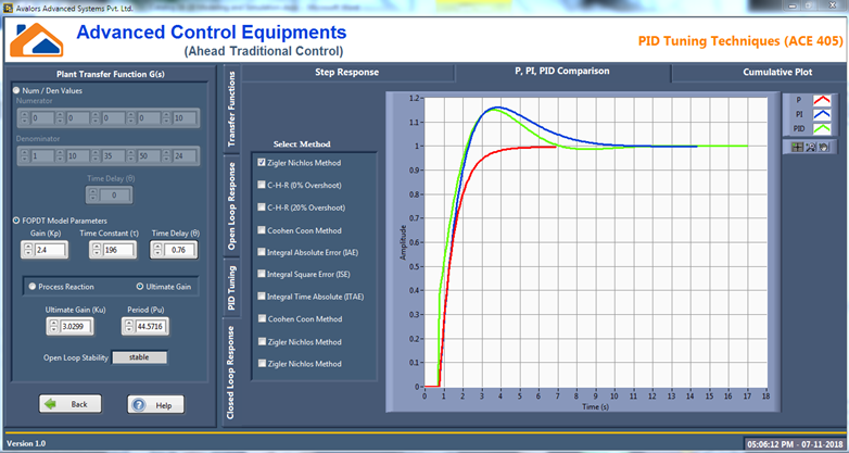
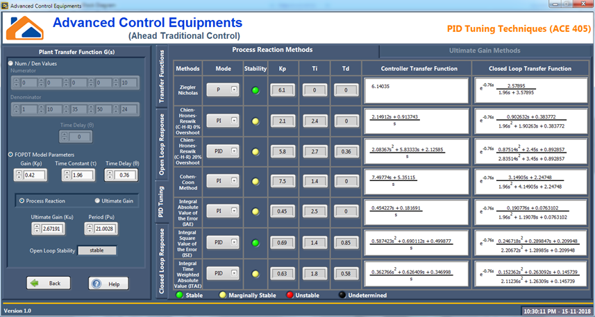
PID Tuning Techniques
PID parameter tuning is an art and this tool is designed to simply the calculations. A clear understanding can be made by observing the response plot of different methods of tuning using this tool. An initial understanding about the process can be made using the open loop analysis. Tuning techniques based on Open loop method (process reaction method) and closed loop method (ultimate gain method) can be performed. User can input transfer function in the form of Numerator/Denominator or as a FOPTD. The following tuning methods are included in the tool.
| Process Reaction Method | Ultimate Gain Method |
|
|
|
|
|
|
|
|
Screenshot
|
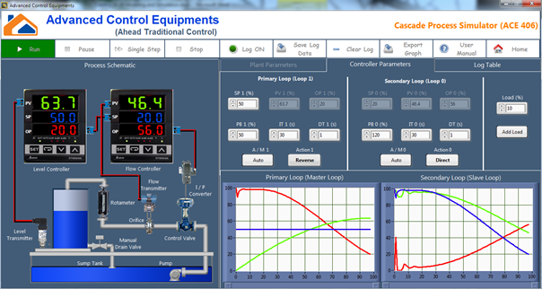
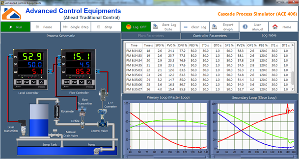
Cascade Process Simulator
In cascade control arrangement the output of primary controller is used as set point of secondary controller. In this simulation tool level process acts as a primary loop and flow process acts as a secondary loop. Plant parameters First principle method is used to derive the differential equations and simulate the process. Typical pilot model parameters in term of tank height, diameter and maximum flow are set as default parameters. Two set of PID parameters can be independently adjusted during simulation to understand the cascade control process. Trend plot will be used to understand the process behavior.
Features
|
|
|
|
|
|
|
|
Screenshot
|
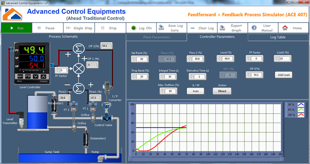
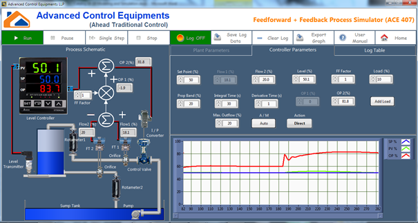
Feedforward + Feedback Simulator
Feedforward technique is used to suppress disturbance by measuring the disturbance parameter and take action before it affect the process. First principle method is used to derive the differential equations and simulate the process. Typical pilot model parameters in term of tank height, diameter and maximum flow are set as default parameters. A level process with level measurement, inflow and outflow measurements are used in this process simulation. Difference between the inflow and outflow will be multiplied by a feedforward factor. This value will be added along with level controller output. If there is any difference between inflow and outflow, the control valve will be opened or closed at the same time instant to compensate the difference. This avoids disturbance before it affects the process.
Features
|
|
|
|
|
|
|
|
Screenshot
|
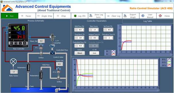
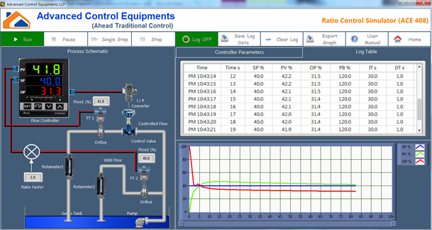
Ratio Control Simulator
This tool is designed to understand ratio control and its applications. Ratio control is utilized in processes where two process variables have to be fed to a process in a definite ratio. For example, in a gas-fired furnace, the flow of gas has to match in a fixed ratio with combustion air, blending of reactants entering a chemical reactor, etc. In Ratio control one variable is controlled in ratio to other. The uncontrolled flow is called as Wild Flow and the flow which will be altered with respect to the Wild Flow is called as controlled flow. The ratio of controllable flow (FT1) to wild flow (FT2) is called as Ratio Factor (RF).
Features
|
|
|
|
|
|
|
|
Screenshot
|
Non-Interacting Level Tank Control Simulator
Process tanks in series will increase dead time and is very common in industrial chemical process applications. High dead time processes are difficult to control with normal PID control algorithm. This simulation tool exhibits the shortcoming of PID control and need of some model based control algorithm like Smith Predictor. In this model, two tanks are connected in series and the outflow of the first tank will be the inflow of the second tank. Both tank levels are measured but second tank level is used as the process variable. The outflow of the first tank can manually be adjusted. The impact of dead time makes the process to oscillate from minimum to maximum value. The non-interacting model of the plant can also be estimated using this simulation tool.
Screenshot

|

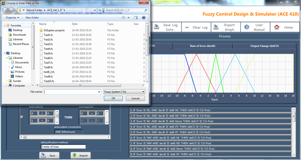
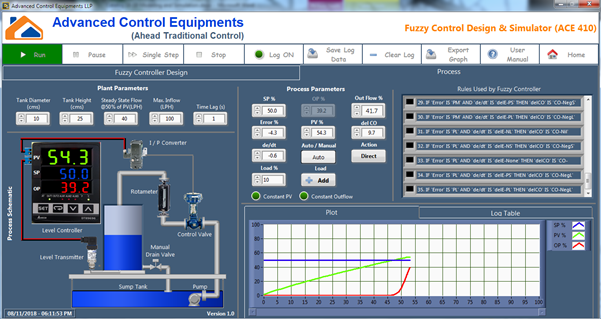
Fuzzy Control Design & Simulator
This tool includes the complete spectrum of fuzzy logic design and implementation in a level process. The process is modeled using first principle method and level value is fed back to the fuzzy controller to control the plant. The simulator consists of two components namely fuzzy controller design and process implementation. Error and error rate are considered as inputs and rate of output is considered as controller output. Number of input and output, shape and range of membership function can be designed by user. Set of rules that relates input-output, defuzzification method can also be designed by the user. Rules and membership graphs are simultaneously displayed for better understanding. In the process simulation, rules triggered, error value, error rate, controller output and output rate will be displayed. This tool can also be used in auto / manual mode, Constant PV and Constant outflow options.
Features
|
|
|
|
|
|
|
|
|
|
Screenshot
|
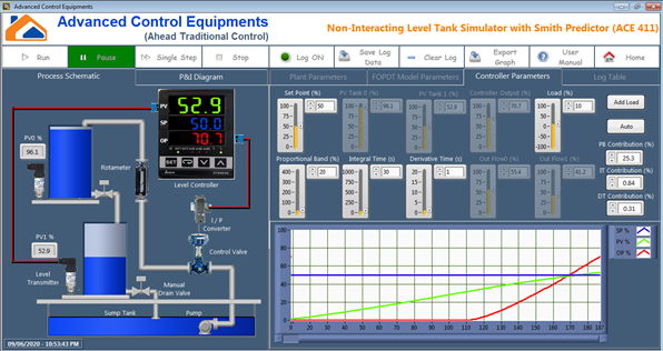
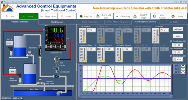
Non-Interacting Level Tank Simulator with Smith Predictor
This tool aims to demonstrate the necessity of Smith Predictor and its implementation. Process tanks in series will increase dead time and is very common in industrial chemical process applications. High dead time processes are difficult to control with normal PID control algorithm. In this simulator, two tanks are connected in non-interacting mode. Both tank levels are measured but second tank level is used as the process variable. The outflow of the first tank can manually be adjusted. The impact of dead time makes the process to oscillate from minimum to maximum value. The non-interacting model of the plant can be estimated using this simulation tool. Once the model is estimated, the model can be fed into the smith predictor structure and control can be visualized. The impact of smith predictor in a high dead time system can be well demonstrated using this simulator.
Features
|
|
|
|
|
|
|
|
|
|
Screenshot
|
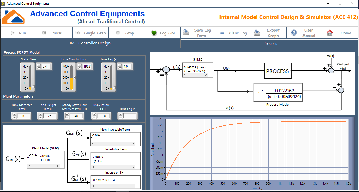
Internal Model Control Design & Simulator
The international model control (IMC) states that a feedback regulator under external disturbances may regain regulation and stability provided a suitably reduplicated model of the disturbance signal is adapted in the feedback path. In other words, if one develops the control scheme based on an exact model of the process, perfect control is theoretically possible. This tool aims to understand the principle of IMC and its implementation. A typical cylindrical level tank parameters are used to simulate the plant using first principle method and a FOPDT model of the same is used in IMC structure. Both the tank parameters and model parameters are user defined. The filter coefficient and bias of the controller can be tuned online to achieve better control.
Features
|
|
|
|
|
|
|
|
Screenshot
|
